
The Concrete Reality Behind the Virtual Cloud
When people speak about “the cloud,” the phrase can make global connectivity sound weightless and almost abstract. In practice, international data depends overwhelmingly on physical infrastructure laid across the seabed. More than 95 percent of international data traffic travels through submarine cables, while satellites serve important but comparatively limited roles for remote access, resilience, broadcasting, and specialized services. Every video call, cloud transaction, software update, and cross-border financial instruction may ultimately pass through a glass fiber buried beneath the ocean.
The scale is difficult to visualize. TeleGeography tracks more than 600 active and planned systems, representing over 1.5 million kilometers of cable in service globally, according to its submarine cable overview. This grid links landing stations on continents and islands, crosses continental shelves, descends into deep ocean basins, and connects the principal data centers that support modern internet services. Major content providers increasingly finance, own, or lease capacity directly, but the physical network remains shared critical infrastructure for carriers, governments, enterprises, researchers, and consumers.
Engineering that network means designing for an environment that combines crushing pressure, corrosive seawater, unstable geology, and constant human activity. A cable may cross calm abyssal plains for thousands of kilometers, then enter a far more dangerous coastal zone where anchors, trawling gear, construction activity, and shipping traffic are concentrated. The most important design decisions therefore concern more than raw capacity. They involve route selection, mechanical protection, electrical reliability, repair access, and the ability to keep traffic moving when one physical path fails.
- Deep-ocean cable sections prioritize low weight, flexibility, and efficient manufacturing.
- Near-shore sections receive heavier armor and are often buried beneath the seabed.
- Landing stations provide optical termination, power feeding, monitoring, and traffic handoff.
- Network operators require route diversity because a high-capacity cable is not automatically a resilient network.
Anatomy of an Abyssal Lifeline Across Marine Depths
A submarine cable is not one uniform product from beach to beach. Its construction changes with depth, seabed composition, fishing activity, and the probability of anchor contact. In deep water, where commercial vessels rarely interact with the seabed, a lightweight cable can be surprisingly slender, sometimes close to the diameter of a garden hose. Near land, the same system may use one or two layers of steel armor, larger protective wires, and burial by a plough or remotely operated vehicle.
At the center are optical fibers made from ultra-pure glass. These fibers carry modulated light, typically across transmission windows around 1,310 or 1,550 nanometers, and are grouped into a fiber unit that protects them from bending and tensile stress. Around that core, manufacturers use water-blocking materials, often including thixotropic petroleum jelly or similar compounds. The material does not function as an optical medium. Its practical purpose is to occupy voids and slow the movement of water if the outer layers are damaged.
Strength and power components sit outside the fiber unit. Steel strength members absorb the mechanical tension imposed during loading, laying, recovery, and repair. A copper conductor carries direct current to submerged repeaters and branching equipment. Around the metallic elements, polymer insulation such as high-density polyethylene provides electrical isolation and resistance to seawater. In high-risk areas, galvanized steel armor adds impact protection and tensile strength. The exact stack varies by supplier and system design, so classifications such as lightweight, lightweight protected, single-armored, and double-armored should be understood as engineering categories rather than universal dimensions.
| Protection level | Typical seabed zone | Primary hazards | Typical protection strategy |
|---|---|---|---|
| Lightweight | Deep abyssal plains | Pressure, abrasion, geological movement | Lay directly on a surveyed seabed with minimal added mass |
| Lightweight protected | Deep or moderate water with some activity | Limited fishing contact, uneven terrain | Additional protective layer and controlled slack |
| Single armored | Continental slopes and coastal approaches | Fishing gear, abrasion, anchor interaction | Steel armor, route engineering, and selective burial |
| Double armored | Shallow, rocky, or heavily trafficked waters | Dragging anchors, trawling, construction, rock impact | Multiple armor layers and deeper burial where feasible |
International standards and manufacturer specifications govern cable construction, testing, laying, and protection. For a useful reference point on submarine cable engineering and deployment, system suppliers describe how wet-plant design, shore ends, terminal stations, and marine installation must be treated as one integrated project. The key operational lesson is straightforward: armor is concentrated where the risk is highest, not distributed uniformly along the entire route.
Delivering Thousands of Volts to the Ocean Floor
Optical fibers carry the information, but the submerged plant still requires electrical power. Long-distance systems use optical repeaters containing erbium-doped fiber amplifiers, or EDFAs, to restore the usable strength of light as it travels across the ocean. Those amplifiers need a continuous supply of direct current for their pump lasers and control electronics. If the electrical feed stops, the optical path may remain physically intact but the system can no longer amplify signals over its designed distance.
Power Feeding Equipment, normally installed at cable landing stations, injects high-voltage direct current into the cable conductor. Depending on cable length and system architecture, equipment ranges commonly from several kilovolts into the tens of kilovolts. Supplier specifications describe land-based systems operating in ranges such as 5 to 18 kilovolts, with shipborne and specialized equipment supporting comparable or higher values. The important engineering principle is not simply high voltage. It is regulated constant current, because each repeater is connected in series along the same powered circuit.
The current can be delivered from one end, from both ends, or through arrangements involving branching units. In a double-end configuration, both landing stations contribute to the power budget and may support operation when one side is unavailable. The PFE monitors voltage, current, insulation resistance, earth-return conditions, and abnormal voltage drops. Redundant converters, batteries, alarms, interlocks, and automatic switching protect the shore-side power system against equipment failures and unsafe operating conditions.
- Single-end feed: one landing station supplies the wet plant, which can simplify operation but concentrates the power source.
- Double-end feed: both ends participate in powering the system, improving flexibility and power margin.
- Branching-unit feed: power is managed across trunk and branch paths, requiring careful isolation and fault coordination.
- Polarity reversal: controlled switching can help operators diagnose faults and configure feeding arrangements without physically accessing the cable.
Sea-earth return arrangements complete the electrical circuit through the surrounding seawater and grounding systems at the landing stations. When a shunt fault occurs, protection logic must distinguish a genuine wet-plant problem from a station-side issue. Operators can isolate sections, reverse polarity, change the feeding end, or reduce power during testing. The system must also prevent hazardous touch potentials and uncontrolled fault currents. This is high-voltage engineering performed across thousands of kilometers, with no practical opportunity to inspect the conductor while it is in service.
Overcoming Signal Decay with Submerged Optical Repeaters
Light travels efficiently through optical fiber, but it does not travel indefinitely without degradation. Absorption, microscopic scattering, connector losses, nonlinear effects, and wavelength-dependent dispersion gradually reduce the signal margin. Modern coherent systems can compensate for some impairments through digital signal processing, but they cannot eliminate the fundamental need for optical gain on very long spans. Repeaters are therefore placed at intervals commonly measured in tens of kilometers, often roughly 50 to 100 kilometers depending on the system design and power budget.
An EDFA uses a short section of fiber doped with erbium ions. Pump lasers energize the erbium, creating a population inversion. Incoming signal photons near the 1,550-nanometer transmission window stimulate the stored energy to be released as additional photons with the same wavelength and phase characteristics. The result is optical amplification without converting every channel into an electrical signal. This matters because the repeater does not need to understand the data format, modulation scheme, or future service mix carried by the fiber.
Submarine repeater housings combine optical precision with pressure-tolerant mechanical design. At deep-ocean depths, ambient pressure can exceed 8,000 pounds per square inch, while the equipment must also tolerate corrosion, heat generated by electronics, cable tension, and a service life commonly designed around 25 years. The repeater is not a simple sealed box. It contains pressure-resistant structures, optical splices, pump redundancy, power interfaces, and materials selected for long-term stability. Research into deep-sea pressure housings, including work documented by the Woods Hole Oceanographic Institution, illustrates how geometry, fatigue, joints, and material composition determine survival under repeated pressure loading.
- Wavelength plans must control chromatic dispersion and nonlinear interaction between channels.
- Amplifier gain must remain sufficiently flat across the operational spectrum.
- Optical signal-to-noise ratio declines cumulatively, so every repeater and splice consumes part of the system margin.
- Pump redundancy and, in advanced designs, pump farming reduce the effect of individual laser failures.
Precision Maritime Splicing When a Deep Line Breaks
Most cable faults are not caused by exotic deep-sea predators. They are usually linked to fishing activity, dragged anchors, or other interaction with the seabed. Natural hazards also matter, including submarine landslides, earthquakes, unstable slopes, and turbidity currents. In politically tense regions, suspected interference and deliberate damage add another layer of risk. Recent assessments have emphasized that inadequate redundancy, limited route diversity, and a shortage of repair vessels can turn an individual fault into a prolonged regional outage. The Recorded Future analysis of cable security describes repair capacity and permitting as important constraints, not merely technical afterthoughts.
Fault localization begins at the landing station. Optical measurement systems send test signals down the affected fiber and analyze reflections or changes in returned light. Coherent optical time-domain reflectometry can provide highly accurate distance estimates by examining phase and amplitude behavior, while electrical resistance and insulation tests help identify conductor faults, shunts, and possible water ingress. Combining optical and electrical readings allows operators to estimate which cable section, repeater span, or joint is involved before a vessel begins recovery work.
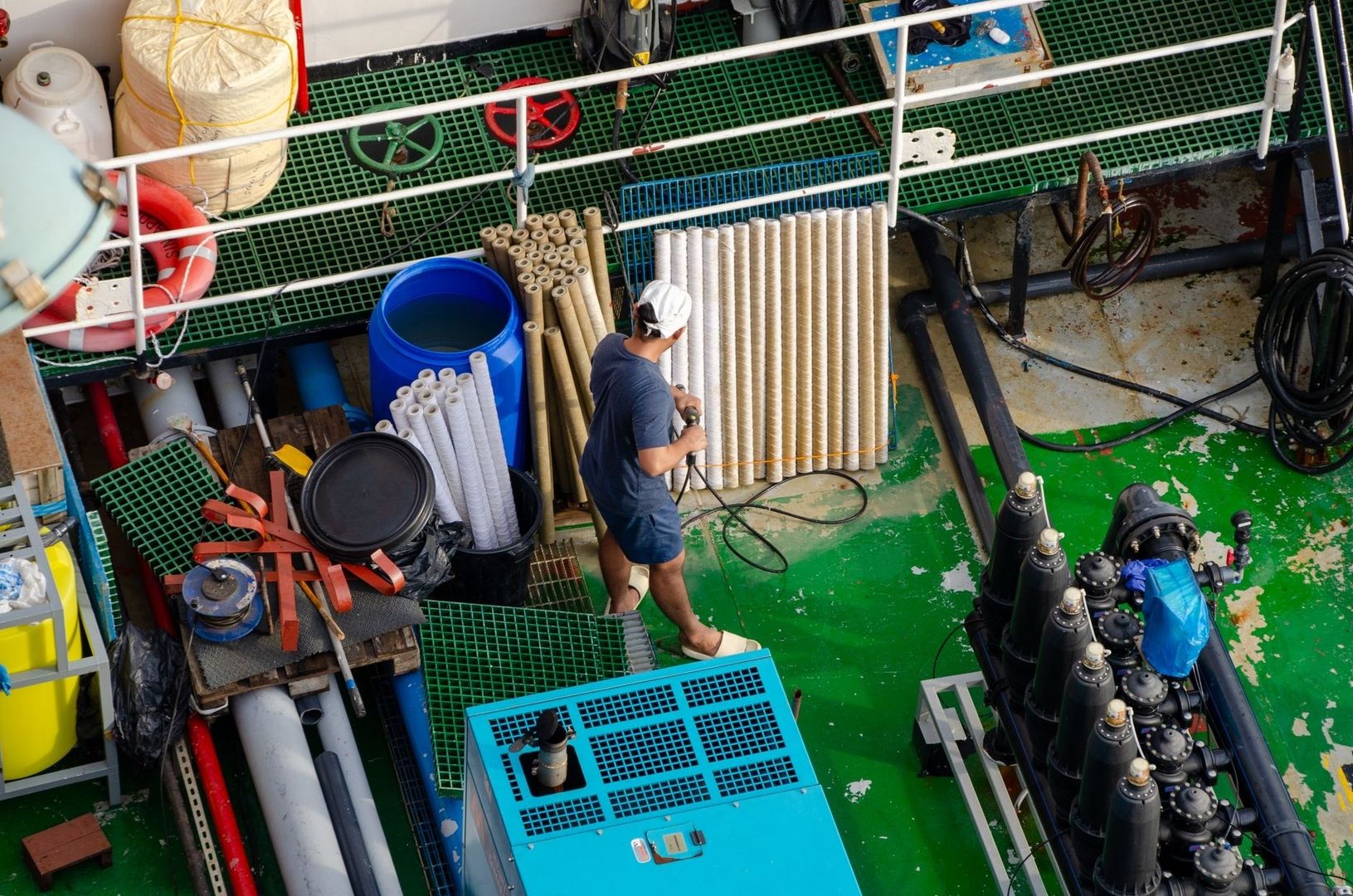
Marine repair is a controlled sequence rather than a single lift-and-replace action. A cable ship receives route data, spare cable, replacement repeaters or joints, grapnels, remotely operated vehicles, and specialized testing equipment. Weather, seabed geometry, permits, fishing schedules, military restrictions, and proximity to other cables all influence the repair plan. In deep water, the crew may need several passes to locate, hook, cut, and recover the cable safely without creating a second fault.
- Confirm the fault: engineers compare optical reflectometry, electrical measurements, traffic alarms, and readings from both landing stations.
- Survey the route: the repair vessel reviews charts and may use sonar or an ROV to inspect the seabed and identify the cable”s actual position.
- Retrieve the cable: a grapnel or ROV brings the damaged section to the surface, with tension carefully controlled to avoid further stress.
- Cut back to sound cable: technicians remove damaged portions and test the remaining fibers, conductors, and armor.
- Perform the splice: in a controlled shipboard environment, optical fibers are aligned and fusion-spliced, while strength and electrical members are rebuilt.
- Install the joint housing: the completed joint is sealed, mechanically tested, electrically tested, and lowered back to the seabed with planned slack.
- Restore and verify service: landing stations conduct end-to-end optical, electrical, and transmission tests before the repaired route returns to normal operation.
A repair can take weeks even when the technical diagnosis is clear. Vessels may be committed to other incidents, spare parts may need to be mobilized across borders, and authorities may delay access to restricted waters. For that reason, resilience is best measured by the network”s ability to reroute traffic, not by the assumption that a cable can always be repaired immediately. Satellites and microwave links can provide partial emergency capacity, but they rarely replace the bandwidth and economics of a major fiber system.
Building Resilient Global Routes on an Unforgiving Ocean Floor
Submarine cable engineering is a synthesis of optical physics, high-voltage electrical design, mechanical protection, marine surveying, fluid and seabed dynamics, and operational logistics. The strongest system is not necessarily the most heavily armored or the one with the highest headline capacity. It is the system that matches protection to local hazards, preserves optical margin, powers repeaters reliably, and has credible repair and traffic-restoration plans.
Route strategy is becoming as important as cable technology. Operators and public authorities are examining concentration around vulnerable corridors, including the Red Sea and the Luzon Strait, while seeking additional landing points, geographically separated paths, diverse terrestrial backhaul, and shared repair capabilities. Future systems will also use technologies such as space-division multiplexing and, potentially, multicore fibers to increase capacity more efficiently. Those advances will expand the digital economy, but resilience will still depend on physical choices made before the first bit crosses the ocean.
- Design for route diversity rather than relying on a single high-capacity corridor.
- Protect coastal approaches aggressively, because most human interaction occurs near shore.
- Maintain sufficient power, optical, and repair spares for the full service life.
- Coordinate operators, governments, vessel owners, and repair providers before an outage occurs.


